Understanding Pt500 RTD Chip Characteristics
Temperature Coefficient and Resistance Values
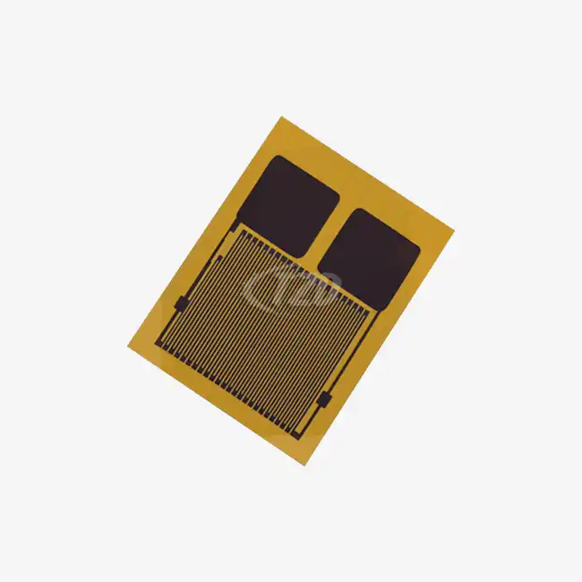
Pt500 RTD chips are renowned for their high accuracy and stability in temperature measurement. These devices typically feature a temperature coefficient of resistance (TCR) of 3850 ppm/°C, adhering to the IEC60751 standard. This specification ensures a consistent and predictable resistance change with temperature variations, enabling precise measurements across a broad range.
When designing circuits with Pt500 RTD chips, it's crucial to consider their nominal resistance value of 500 ohms at 0°C. This higher resistance, compared to Pt100 sensors, offers improved sensitivity and reduced lead wire effects. However, it also necessitates careful consideration of excitation currents to minimize self-heating.
Physical Dimensions and Packaging
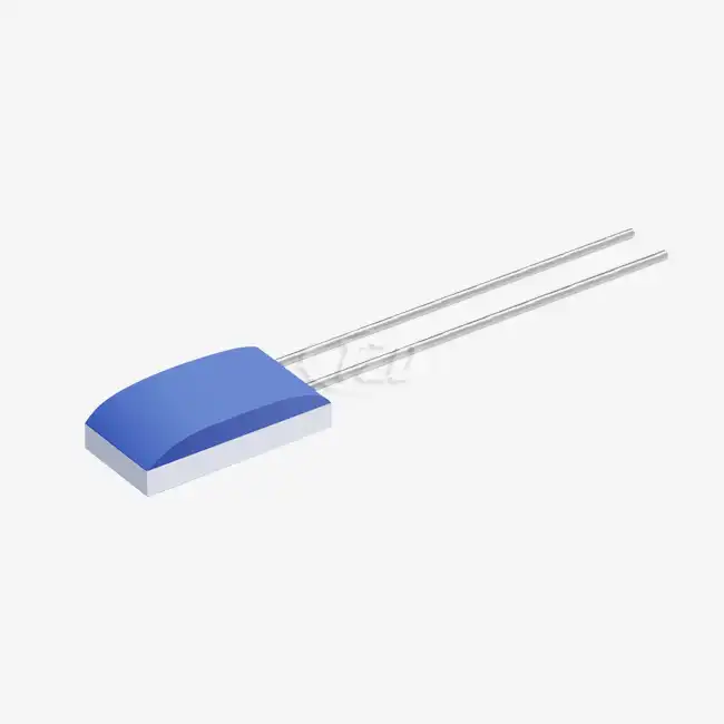
Modern Pt500 RTD chips come in compact sizes, often as small as 2.0mm x 2.3mm x 1.0mm. These miniature dimensions allow for integration into space-constrained applications without compromising performance. When selecting a Pt500 RTD chip for your circuit, consider the packaging options available, such as vacuum plastic packaging, which can enhance protection against environmental factors.
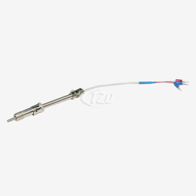
The lead specifications of Pt500 RTD chips typically include lengths around 10 mm and diameters of 0.2 mm. These leads are often made of platinum-nickel wire, though alternatives like silver-palladium, pure platinum, or pure silver may be available. The choice of lead material can affect the overall performance and durability of your temperature sensing circuit.
Performance Parameters
Several key performance parameters should guide your circuit design decisions when working with Pt500 RTD chips:
- Insulation Resistance: Typically 100 MΩ at 20°C, decreasing to >2 MΩ at 500°C
- Operating Current: Generally between 0.1–0.7 mA, with self-heating effects to be considered
- Long-Term Stability: ≤±0.04% resistance drift of R₀ (0°C reference) after 1000 hours at 500°C
- Response Time: In water flow (V=0.4 m/s), t₀.₅ = 0.05 s, t₀.₉ = 0.15 s; In airflow (V=2 m/s), t₀.₅ = 3 s, t₀.₉ = 10 s
- Self-Heating Coefficient: Approximately 0.4°C/mW at 0°C
- Vibration Resistance: ≥40g acceleration (frequency range: 10–2000 Hz)
- Shock Resistance: ≥100g acceleration (8 ms half-sine wave)
These specifications underscore the robustness and precision of Pt500 RTD chips, making them suitable for demanding applications in industrial, medical, automotive, and aerospace sectors.

Optimizing Circuit Design for Pt500 RTD Chips
Excitation Current and Self-Heating Considerations
One of the primary challenges in designing circuits with Pt500 RTD chips is managing the excitation current to balance measurement sensitivity with self-heating effects. The higher resistance of Pt500 chips compared to their Pt100 counterparts allows for lower excitation currents, typically in the range of 0.1 to 0.7 mA. This reduced current helps minimize self-heating, which can introduce measurement errors.
To optimize your circuit design, consider implementing a current source with precision control. Pulsed excitation techniques can further reduce self-heating by applying current only during measurement intervals. When calculating self-heating effects, use the self-heating coefficient (e.g., 0.4°C/mW at 0°C) to estimate temperature rise based on applied power.
Lead Wire Compensation Techniques
While Pt500 RTD chips offer reduced lead wire effects compared to lower resistance RTDs, proper compensation remains crucial for high-accuracy applications. Three-wire and four-wire configurations are commonly employed to mitigate lead resistance effects:
- Three-wire configuration: Provides lead resistance compensation by using two leads for current and one for voltage measurement.
- Four-wire configuration: Offers the highest accuracy by completely separating current and voltage paths, eliminating lead resistance effects.
When designing your circuit, consider the trade-offs between accuracy requirements and complexity. For applications requiring utmost precision, the four-wire method is preferred, despite the additional wiring and circuitry involved.

Signal Conditioning and Amplification
The small voltage changes produced by Pt500 RTD chips necessitate careful signal conditioning and amplification. Consider these approaches to enhance signal quality:
- Wheatstone bridge configuration: Balances the RTD resistance against precision reference resistors, providing a differential output that can be amplified.
- Precision instrumentation amplifiers: Offer high common-mode rejection and low noise, ideal for amplifying the small differential signals from RTD bridges.
- Analog-to-Digital Converters (ADCs): Select high-resolution ADCs (20-bit or higher) to capture the full range of temperature measurements without loss of precision.
Implementing these signal conditioning techniques ensures that the valuable data from your Pt500 RTD chip is accurately captured and processed, maintaining the sensor's inherent precision throughout the measurement chain.
Advanced Considerations for High-Performance Applications
Temperature Linearization Strategies
While Pt500 RTD chips offer excellent linearity compared to many other temperature sensors, their response is not perfectly linear across their entire operating range. For applications requiring extreme precision, consider implementing linearization techniques:
- Look-up tables: Store pre-calculated correction factors in memory for rapid, real-time linearization.
- Polynomial approximation: Use higher-order polynomials to model the RTD response curve more accurately.
- Segmented approximation: Divide the temperature range into segments, applying different linearization methods to each for optimized accuracy.
These linearization strategies can be implemented in software or hardware, depending on your system's processing capabilities and response time requirements.
Noise Reduction and EMI Protection
The high sensitivity of Pt500 RTD circuits makes them susceptible to electrical noise and electromagnetic interference (EMI). Implement these techniques to enhance signal integrity:
- Differential signaling: Use fully differential signal paths to reject common-mode noise.
- Proper shielding: Employ shielded cables and enclosures to minimize EMI pickup.
- Ground plane design: Implement a solid ground plane in your PCB design to reduce ground loop effects.
- Filter implementation: Use analog and digital filtering techniques to remove high-frequency noise without compromising response time.
By addressing these noise and EMI concerns, you can ensure that your Pt500 RTD circuit maintains its high accuracy even in electrically noisy environments.
Calibration and Drift Compensation
To achieve and maintain the highest possible accuracy in your Pt500 RTD-based temperature measurement system, consider implementing advanced calibration and drift compensation techniques:
- Multi-point calibration: Calibrate your system at multiple temperature points across its operating range to account for non-linearities.
- Auto-calibration circuits: Implement switching circuits that periodically measure known reference resistances to compensate for system drift.
- Temperature cycling: Subject your circuit to temperature cycling during calibration to account for hysteresis effects.
- Long-term stability monitoring: Implement periodic recalibration schedules based on the long-term stability specifications of your Pt500 RTD chip (e.g., ≤±0.04% resistance drift after 1000 hours at 500°C).
These advanced calibration strategies ensure that your temperature measurement system maintains its accuracy over time and across varying environmental conditions.
Conclusion
Designing circuits with Pt500 RTD chips demands a meticulous approach that balances precision, reliability, and practical considerations. By understanding the unique characteristics of these sensors and implementing advanced circuit design techniques, engineers can create high-performance temperature measurement systems suitable for the most demanding applications.
From managing self-heating effects to implementing sophisticated linearization and calibration strategies, each aspect of the design process contributes to the overall accuracy and reliability of the final system. As temperature sensing requirements continue to evolve across industries, Pt500 RTD chips remain at the forefront of precision measurement technology, offering unparalleled stability and accuracy. For more information on incorporating Pt500 RTD chips into your designs or to discuss custom solutions for your specific application, please contact us at sales11@xatzd.com.